ZEngineStudios
ABOUT ME
I am an independent developer primarily focused on graphics-related work. I am passionate about technology and strive to bring more cool innovations. Recently, I have been deeply immersed in implementing Nanite in Unity.
Nanite Like Virtual Geometry
A Unity package inspired by Nanite, enabling massive, detailed asset rendering with seamless LOD management and virtualized geometry.
And it’s a fully GPU-driven solution for Unity. I am developing this project alone in my spare time, and it excites and inspires me.
Supported Features:
-
Meshlet LOD and BVH node Generation
-
Meshlet LOD hierarchy
-
Nanite-like BVH tree
-
Instance GPU frustum and occlusion culling
-
BVH Node GPU frustum and occlusion culling and lod travel
-
Meshlet GPU frustum and occlusion culling
-
Hardware rasterizer
-
Visibility buffer
-
Shadow support including point light shadow and directional light shadow (CSM)
-
Deferred Material
-
Per Chunk Material Culling
-
Single-phase rasterizer
-
Support opaque object only
-
Programingable rasterier (Alpha Test)
-
Skinned mesh
-
rendering layer
-
Deferred shading only
-
Per-object GI is supported (per-object light probe, reflection probe and Lightmap)
Not Support Yet:
-
No software rasterier
-
No two phase Occlusion Culling
-
No Streaming
-
No Compression currently
-
Not Support Unity Terrain (no plan to support)
Document
Setup Guide
Using this project is very simple:
Automatically
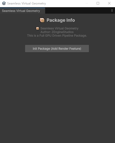
1、Use URP. It is recommended to start with an empty Core URP project. When opening for the first time or clicking [Tools/Show Seamless Virtual Geometry Setup Window], the following window will appear. Click [Init Package] to initialize.”
Manually
1、Use URP. It is recommended to start with an empty Core URP project and set the Rendering Path to Deferred (this setting is usually located in “Assets/Settings/PC_Renderer.asset”).
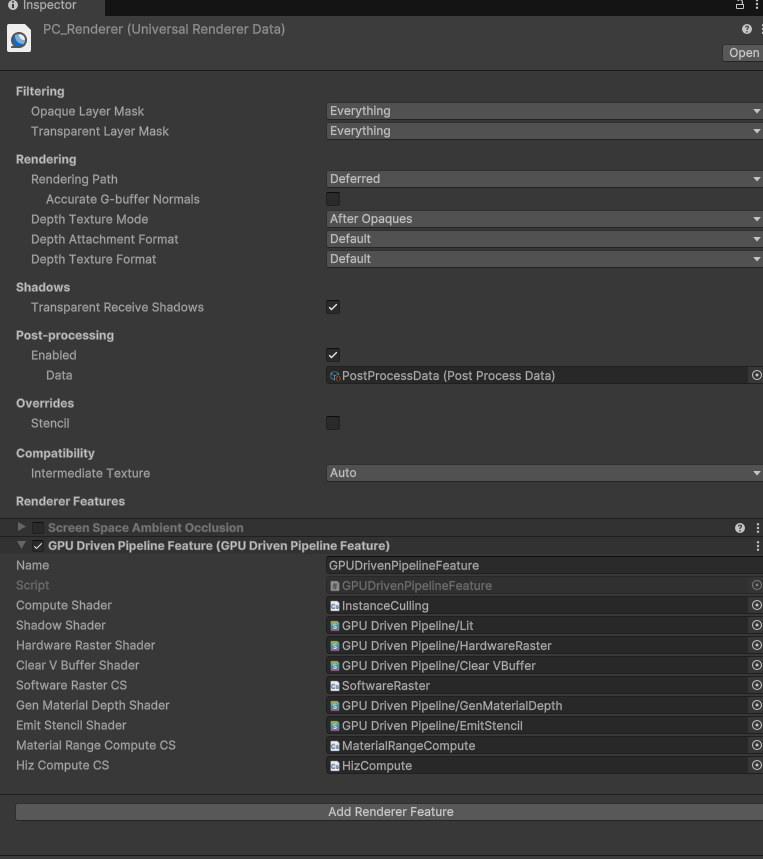
2、Open PC_Renderer.asset from step 1 and add a render feature named GPU Driven Pipeline Feature. And Assgin shaders.
How to bake Scene
Drag Assets/GpuDrivenPipeline/Runtime/Prefabs/GPUDrivenPipelineContext.prefab into the Scene Hierarchy and configure it. The default settings should work with the default URP.
Use the configured shaders to create your scene. Then, add the GPU Driven Scene component to any GameObject and click Bake Scene to bake it into a VG scene.
If you want to continue editing the scene, click Revert Scene.
⚠️ Note: It is recommended to place all VG objects under a single root parent for better scene management and clarity.
If you’re using URP, the simplest way is to replace all materials’ Lit shader with our GPUDrivenPipelineLit.shader, then simply click ‘Bake Scene’.”
Alse see https://www.youtube.com/watch?v=Mvty08Og7Lo
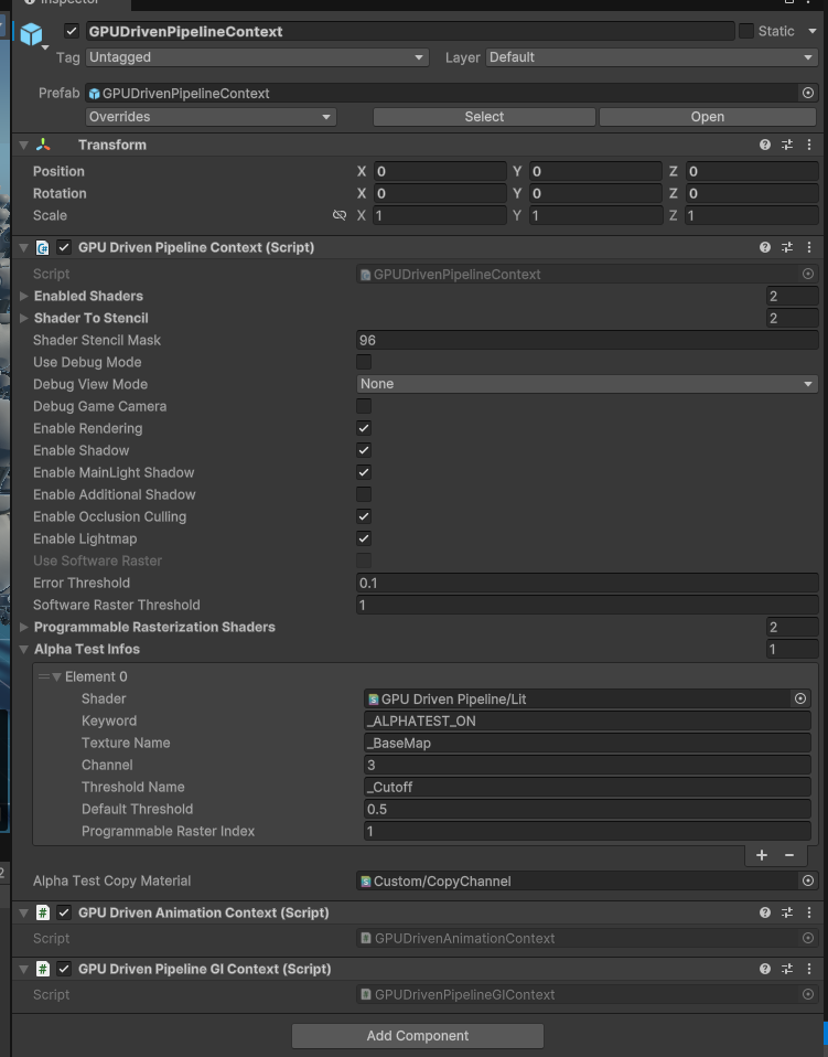 GPUDrivenPipelineContext Settings
-
Enabled Shader: Stores the shaders that need to be baked. GPUScene will traverse all renderers in the scene that use shaders from this list and perform baking. ⚠️ Note: The shader must be compatible with our VG. See the section below on modifying shaders for VG compatibility.
-
Shader to Stencil: Stores the stencil values to be written by the corresponding shaders in the list. This is usually used in deferred rendering to distinguish lighting models (e.g., Lit, Simple Lit, and more).
-
Shader Stencil Mask: Stores the stencil mask used by URP, with 96 being the default value.
-
Enable Shadow: Toggles shadows for VG objects.
-
Enable Occlusion Culling: Toggles OC.
-
Use Software Raster: Currently unsupported. In Unity, 64-bit atomic operations require DX12 and DXC support. Unfortunately, Unity’s DXC support is quite poor.
-
Error Threshold: Sets the error threshold (measured in pixels), though it is not always highly accurate. You can adjust this value to observe the effects—higher values will make lower LOD models appear more easily.
-
Software Raster Threshold: Current just simply drop the meshlet that smaller than the value.
-
Alpha Test Info: The actual programmable rasterization shader is determined based on the shader’s name and its keyword combination. If the keyword is empty, it means the shader always uses the programmable rasterization shader corresponding to that programmable raster index. TextureName refers to the texture attribute name used in the material, channel specifies which channel represents the alpha channel (0–3 corresponding to RGBA), and Threshold Name indicates the attribute name that defines the cutoff threshold.
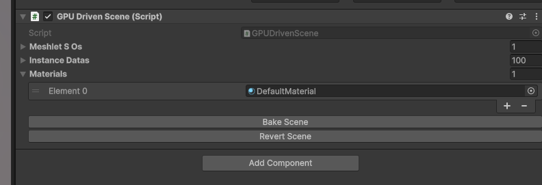 GPU Driven Scene as shown in the image above.
Skinned Mesh Support
For skeletal animation, we provide GPU skinning to support movement and deformation. Our solution is similar to vertex skinning. The advantage is that for multiple different animations of the same mesh, we don’t modify the original vertex buffer—instead, we skin directly based on the skeleton. This reduces unnecessary GPU memory usage. The downside is that in multi-pass scenarios (e.g., shadow and draw passes), skinning needs to be performed multiple times. This approach is a trade-off between memory consumption and runtime performance.
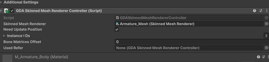
For Skinned Mesh Renderers, similar to regular renderers, no additional handling is generally required. During scene baking, a GDASkinnedMeshRendererController will be attached under the corresponding Skinned Mesh Renderer. If you need to update the position every frame, enable ‘Need Update Position’ — this is suitable for scenarios where frequent position updates are needed. In the case shown in the SkinnedMeshDemo scene, where multiple instances play the same animation, simply assign the ‘Used Refer’ to the controller that should follow the animation.
Alse see https://www.youtube.com/watch?v=wklo_K_ixQI&t=2s
Configure with your own shader
1、Add Render State Commands, And Add Shader Properties
            [HideInInspector] _ZWrite("__zw", Float) = 1.0
            [HideInInspector] _ZTest("__zt", Float) = 4.0
              ....
              ....

          Pass
          {
                Name "GBuffer"
                Tags
                {
                    "LightMode" = "UniversalGBuffer"
                }

                // Render State Commands
                ZWrite[_ZWrite]
                ZTest[_ZTest]
              ..
          }
2、For GBuffer pass , Change vertex pass below.
                #pragma multi_compile _ GPU_DRIVEN_PIPELINE
                #pragma multi_compile _ GPU_DRIVEN_PIPELINE_DEBUG // only if you need debug mode
                #pragma multi_compile _ _VBUFFER_MATERIAL_DRAW
                #include "./ShadingUtils.hlsl"
#ifdef _VBUFFER_MATERIAL_DRAW

                struct AttributesQuadCull
                {
                    uint instanceID:SV_InstanceID;
                };

                Varyings MaterialDrawVertQuadCull(AttributesQuadCull input, uint vertexID : SV_VertexID)
                {
                    Varyings output;
                    UNITY_SETUP_INSTANCE_ID(input);
                    UNITY_INITIALIZE_VERTEX_OUTPUT_STEREO(output);

                    float4 pos = GetQuadVertexPosition(vertexID);
                    float2 uv  = GetQuadTexCoord(vertexID);

                    uint instanceID = UNITY_GET_INSTANCE_ID(input);

                    float2 scaleAndOffset = _MaterialTileStrideAndTileCount.xy;
                    float2 tileCount = _MaterialTileStrideAndTileCount.zw;
                    int curTileX = instanceID % int(tileCount.x);
                    int curTileY = instanceID / int(tileCount.x);
                    float2 offset = float2(curTileX, curTileY) * scaleAndOffset;


                    uint materialRange = _MaterialDepthRange.Load(int3(curTileX, curTileY, 0));
                    uint materialRangeMin = materialRange & 0x0000FFFF;
                    uint materialRangeMax = (materialRange  >> 16) & 0x0000FFFF;
                    // todo test
                    if(materialRangeMax < materialRangeMin || _MaterialID < materialRangeMin || _MaterialID > materialRangeMax)
                    {
                        // to INF
                        output.positionCS = 1000000.0f;
                        output.uv = float2(0, 0);
                        return output;
                    }

                    output.positionCS    = pos;
                    output.positionCS.xy = output.positionCS.xy * scaleAndOffset + offset;
                    output.uv   = uv * scaleAndOffset + offset;

                    output.positionCS.xy = output.positionCS.xy * float2(2.0f, -2.0f) + float2(-1.0f, 1.0f); //convert to -1..1

                    output.positionCS.z = EncodeMaterialID(_MaterialID);
                    return output;
                }


                Varyings CustomLitGBufferPassVertex(AttributesQuadCull input, uint vertexID : SV_VertexID)
                {
                    Varyings output = (Varyings)0;

                    return MaterialDrawVertQuadCull(input, vertexID);
                }
#endif
3、For the Fragment Shader:
                FragmentOutput CustomLitGBufferPassFragment(Varyings input)
                {

                    UNITY_SETUP_INSTANCE_ID(input);
                    UNITY_SETUP_STEREO_EYE_INDEX_POST_VERTEX(input);

                    // Recreate Data From VBuffer
                    float2 ddxUV = 0;
                    float2 ddyUV = 0;
                    float2 ddxUV2 = 0;
                    float2 ddyUV2 = 0;
                    float2 outUV2 = 0;
                    uint perInstanceID = 0;
                    uint outRenderingLayer=0;
                    InstanceGIData instanceGIData = (InstanceGIData) 0;
                    #ifdef _VBUFFER_MATERIAL_DRAW
                        int meshletIndex = 0;
                        int triangleID = 0;

                        #if defined(REQUIRES_WORLD_SPACE_TANGENT_INTERPOLATOR)
                            ReCreateVertOutDataFromVBuffer(input.uv, input.uv, input.positionWS, input.normalWS, input.tangentWS,
                                input.positionCS.z, meshletIndex, triangleID, ddxUV, ddyUV, perInstanceID, outUV2, ddxUV2, ddyUV2, outRenderingLayer);
                        #else
                            float4 outTangentWS = 0;
                            ReCreateVertOutDataFromVBuffer(input.uv, input.uv, input.positionWS, input.normalWS, outTangentWS,
                                input.positionCS.z, meshletIndex, triangleID, ddxUV, ddyUV, perInstanceID, outUV2, ddxUV2, ddyUV2, outRenderingLayer);
                        #endif
                        instanceGIData = InstanceGIDataBuffer[perInstanceID];
                        // we skip vertx shader so has to tilling here, also should scale ddx, ddy
                    #endif
                    ...
                    ...

                    // only if need debug Begin
                    #ifdef GPU_DRIVEN_PIPELINE_DEBUG
                    #if defined(_VBUFFER_MATERIAL_DRAW)
                        uint debugIndex = 0;
                        if(_GpuDrivenPipelineDebugMode < 1.5)
                            debugIndex = meshletIndex;
                        else if(_GpuDrivenPipelineDebugMode < 2.5)
                            debugIndex = triangleID;
                        else
                            debugIndex = _MaterialID;
                        float4 debugColor[10] = {float4(1, 0, 0, 1),
                            float4(0, 1, 0, 1), float4(0, 0, 1, 1), float4(1, 1, 0, 1), float4(1, 0, 1, 1),
                            float4(0, 1, 1, 1), float4(1, 1, 1, 1), float4(0.5, 0.5, 0.5, 1), float4(0.5, 0, 0, 1), float4(0, 0.5, 0, 1)};
                        surfaceData.emission = debugColor[debugIndex % 10];
                        surfaceData.albedo = 0;
                    #endif
                    #endif
                    // only if need debug End

                    ...
                    ...
                }
4、for other attribute you need to interpolate from vertx, please refer to function InterpolateWithDeriv in “Assets/GpuDrivenPipeline/Runtime/Shaders/VBuffer/VBufferUtils.hlsl”.
void ReCreateVertOutDataFromVBuffer(float2 uv, out float2 outUV, out float3 outPoitionWS, out float3 outNormalWS,
    out float outDepth, out int outMeshletIndex, out int outTriangleID)
{
#ifdef _USE_SOFT_RASTERIZATION
    uint pixelValue =  _VisBuffer.Load(int3(uv * _ScreenParams.xy, 0)).y;
#else
    uint pixelValue =  _VisBuffer.Load(int3(uv * _ScreenParams.xy, 0));
#endif
    uint cullingedNodeIndex = (pixelValue >> 7) & 0x1FFFFFF;
    uint triangeID = pixelValue & 0x7F;
    CulledNodeInfo culledNodeInfo = CulledMeshLetListForShading[cullingedNodeIndex];
    uint meshletIndex = culledNodeInfo.meshletIndex;
    NaniteMeshletNode meshlet = GetMeshletData(meshletIndex);
    InstanceData instanceData = InstanceDataBuffer[culledNodeInfo.instanceID];
    ModelData modelData = GetModelData(instanceData.modelDataIndex);
    uint modelDataIndexOffset = modelData.indicesOffset;
    uint modelDataVertexOffset = modelData.vertexOffset;

    float4 pt[3];
    VertexBufferLayout vertexInfo[3];
    float3 posWS[3];
    float3 normalWS[3];
    UNITY_UNROLL
    for(int i=0; i<3; ++i)
    {
        uint vertexID = triangeID * 3 + i;
        uint globalIndex = meshlet.firstIndexOffset + modelDataIndexOffset + vertexID;
        uint globalVertexIndex = indicesBuffer[globalIndex] + modelDataVertexOffset;
        vertexInfo[i] = vertexBuffer[globalVertexIndex];
        posWS[i] = mul(instanceData.worldTransfrom,  float4(vertexInfo[i].position, 1.0)).xyz;
        normalWS[i] = normalize(mul(instanceData.worldTransfrom, vertexInfo[i].normal).xyz);
        pt[i] = mul(UNITY_MATRIX_VP, float4(posWS[i], 1.0));
        pt[i] /= pt[i].w;
    }

    float2 winSize = _ScreenParams.xy;

#if UNITY_UV_STARTS_AT_TOP
    uv.y = 1.0f - uv.y;
#endif

    float2 pixelNdc = uv * 2.0f - 1.0f;

    BarycentricDeriv bary = CalcFullBary(pt[0], pt[1], pt[2], pixelNdc, winSize);
    // todo add your own attribute like below
    outUV = InterpolateWithDeriv(bary, vertexInfo[0].uv, vertexInfo[1].uv, vertexInfo[2].uv);
    outPoitionWS = InterpolateWithDeriv(bary, posWS[0], posWS[1], posWS[2]);
    outNormalWS = normalize(InterpolateWithDeriv(bary, normalWS[0], normalWS[1], normalWS[2]));
    outDepth = InterpolateWithDeriv(bary, pt[0].z, pt[1].z, pt[2].z).x;
    outMeshletIndex = meshletIndex;
    outTriangleID = triangeID;
}
4、For UV sampling, use SAMPLE_TEXTURE2D_GRAD with the ddxUV and ddyUV parameters, as demonstrated in the SampleAlbedoAlpha function. For details, refer to Assets/GpuDrivenPipeline/Runtime/Shaders/Lit/URPShaderLib/SurfaceInput.hlsl.
inline void InitializeStandardLitSurfaceData(float2 uv, out SurfaceData outSurfaceData, float2 ddxUV=0, float2 ddyUV=0)
{
    float2 tilling1 = _Tiling1;
    float2 tilling2 = _Tiling2;
    float2 uv1 = tilling1 * uv;
    float2 uv2 = tilling2 * uv;
    half4 albedo1 = SampleAlbedoAlpha(uv1, TEXTURE2D_ARGS(_Albedo1, sampler_Albedo1), ddxUV * tilling1, ddyUV * tilling1);
    half4 albedo2 = SampleAlbedoAlpha(uv2, TEXTURE2D_ARGS(_Albedo1, sampler_Albedo1), ddxUV * tilling2, ddyUV * tilling2);
    half3 normal1 = SampleNormal(uv1, TEXTURE2D_ARGS(_Normal1, sampler_Normal1), 1.0, ddxUV * tilling1, ddyUV * tilling1);
    half3 normal2 = SampleNormal(uv2, TEXTURE2D_ARGS(_Normal1, sampler_Normal1), 1.0, ddxUV * tilling2, ddyUV * tilling2);
    #ifdef _VBUFFER_MATERIAL_DRAW
    half4 specular1 = SAMPLE_TEXTURE2D_GRAD(_Specular1, sampler_Specular1, uv1, ddxUV * tilling1, ddyUV * tilling1);
    half4 specular2 = SAMPLE_TEXTURE2D_GRAD(_Specular2, sampler_Specular2, uv2, ddxUV * tilling2, ddyUV * tilling2);
    float mask = SAMPLE_TEXTURE2D_GRAD(_Mask, sampler_Mask, uv, ddxUV, ddyUV).a;
    #else
    half4 specular1 = SAMPLE_TEXTURE2D(_Specular1, sampler_Specular1, uv1);
    half4 specular2 = SAMPLE_TEXTURE2D(_Specular2, sampler_Specular2, uv2);
    float mask = SAMPLE_TEXTURE2D(_Mask, sampler_Mask, uv).a;
    #endif

    half4 albedoAlpha = lerp(albedo1, albedo2, mask);
    half3 normalTS = normalize(lerp(normal1, normal2, mask));
    half4 specGloss = lerp(specular1, specular2, mask);


    outSurfaceData.alpha = 1.0;
    outSurfaceData.albedo = albedoAlpha.rgb;
    outSurfaceData.albedo = AlphaModulate(outSurfaceData.albedo, outSurfaceData.alpha);

    outSurfaceData.metallic = half(0.0);
    outSurfaceData.specular = specGloss.rgb;

    outSurfaceData.smoothness = specGloss.a;
    outSurfaceData.normalTS = normalTS;
    outSurfaceData.occlusion = SampleOcclusion(uv, ddxUV, ddyUV);
    outSurfaceData.emission = 0;

#if defined(_CLEARCOAT) || defined(_CLEARCOATMAP)
    half2 clearCoat = SampleClearCoat(uv);
    outSurfaceData.clearCoatMask       = clearCoat.r;
    outSurfaceData.clearCoatSmoothness = clearCoat.g;
#else
    outSurfaceData.clearCoatMask       = half(0.0);
    outSurfaceData.clearCoatSmoothness = half(0.0);
#endif

}
half4 SampleAlbedoAlpha(float2 uv, TEXTURE2D_PARAM(albedoAlphaMap, sampler_albedoAlphaMap), float2 ddxUV, float2 ddyUV)
{
    #ifdef _VBUFFER_MATERIAL_DRAW
    return half4(SAMPLE_TEXTURE2D_GRAD(albedoAlphaMap, sampler_albedoAlphaMap, uv, ddxUV, ddyUV));
    #else
    return half4(SAMPLE_TEXTURE2D(albedoAlphaMap, sampler_albedoAlphaMap, uv));
    #endif
}
GC Free
To avoid making intrusive modifications to URP, I use reflection to call certain functions and properties during the shadow rendering phase of VG.
To enable a GC-free function call approach, I use two dll to differentiate between the GC-free and non-GC-free versions.
Additionally, copy the URP package to your local project and modify any private or internal properties and methods causing compilation errors by changing them to public.
Technical Details
Meshlet Generation
The meshlets of Virtual Geometry are generated using meshoptimizer. Each LOD level reduces the triangle count by half, similar to Nanite. Edge locking is applied only at the boundaries between adjacent levels to ensure smooth transitions without sudden visual artifacts.
Processing Pipeline:
- Initial Simplification: The algorithm first attempts to simplify the mesh using meshopt_simplify, which preserves boundaries and topology. If the triangle count can be reduced to 50%, the simplification is applied.
- Fallback Simplification: If the triangle count cannot be reduced sufficiently, meshopt_simplifySloppy is used instead. This method does not guarantee boundary and topology preservation but ensures the target triangle reduction is achieved. As a result, at the lowest LOD levels, seams and isolated mesh elements may disappear.
- Potential Optimizations: The algorithm still has much room for improvement. The author of meshoptimizer (zeux) provides an API that allows explicitly specifying edges that need to be locked. This can be used to ensure better boundary preservation between adjacent LOD levels. Using this API should result in a higher-quality simplification (TODO).
The current version of BVH traversal is similar to the terrain LOD traversal used in Far Cry 5. I dispatch a compute shader with 1024 threads and traverse the LODs, swapping at each level.
About BVH Travel
This may not be the most efficient approach, and the current version does not include multi-view processing (though implementing it should not be too difficult). As a result, the CPU overhead for shadows is relatively high.
About Mobile
The mobile version is now working properly (Android Vulkan), tested on OnePlus 7 Pro.
That said, as everyone knows, Nanite has not been optimized for mobile either. Given the bandwidth limitations on mobile devices, the performance may not be ideal.In my tests, VG even caused a performance drop on mobile.For mobile platforms, more time may be needed for optimization.
Contact Me
If you encounter any issues or have any suggestions while using this project, please feel free to email me.
If you encounter a bug, please include a minimal reproducible demo, which should contain: Code Minimal reproducible scene URP version Unity version Description of the issue and error stack trace